


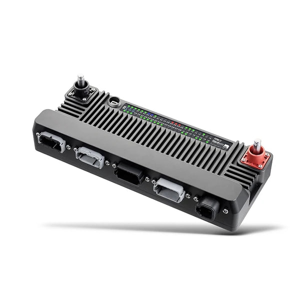


PDM28
A PDM (Power Distribution Module) is a device used to replace conventional relays and fuses in a vehicle electrical system. The Hardwire Electronics PDM takes inputs from physical switches, analogue voltages, or the CAN bus, and provides power as needed to different attached loads - such as radiator fans, lights or pumps. The current being drawn from each connected load is continuously monitored. If the measured current is too high due to a fault, the PDM switches off the respective output to prevent further damage to the wiring loom or the connected device. The PDM can then retry the output to see if the fault has cleared.
Solid State technology ensures maximum reliability, without the drawbacks of conventional mechanical relay and fuse systems. Vibration, water and dirt are no longer a problem.
Our PDMs have been used in a range of applications - from drilling machines in ore mines, to top-spec drag race cars, to EV trucks, and even in industrial greenhouses to actuate ventilation windows. Allowing the user to configure the PDM to suit their own needs is one of its greatest strengths.
Features
General Features
-
Size: 318x124x58mm.
-
Weight: 1640g.
-
Operating Voltage: 12/24V.
-
Operating Temperature: -55°C to 90°C (-67°F to 194°F).
-
Construction: Machined Aluminium, Media Blasted and Anodised Black.
-
IP Rating: IP67 water and dust resistant.
-
Connectors: 2x DTM 12-Pin, 2x DT 12-Pin, 1x DTP 4 Pin.
-
Quick Release Radlok Connectors.
-
Update Rate: Up to 2000Hz.
-
USB connection to a Windows PC. No external programmer is required.
-
50x RGB LED Indicators.
-
Free and easy to use configuration software.
-
9-Axis IMU

Inputs
-
16x Analogue inputs, which can also serve as digital inputs.
-
Measurement Range: Each input can measure between 0V-25V.
-
Measurement Resolution: 16-Bit, or 0.001V
-
Fully protected for input voltages from -24V to 40V.
-
Integrated Software Selectable 10K Pull up/down resistors allow for positive and ground switching.
-
Inputs can be configured as Momentary or Latched, allowing for different types of switches to be used.
-
Hysteresis voltage can be added for extra resilience to voltage noise.
-
Frequency Measurement up to 300Hz with automatic triggering.
-
Software defined filters.

Outputs
-
4x High/Low side, reverse current blocking outputs capable of supplying 30A continuous and 100A Peak
-
6x High/Low side, reverse current blocking outputs capable of supplying 20A continuous and 80A Peak
-
18x High/Low side outputs capable of supplying 20A continuous and 80A Peak.
-
200A combined output maximum current
-
Protection: Each output is overcurrent, overtemperature, load dump and reverse polarity protected.
-
Output Current Control Steps: 100mA (0.1A).
-
Output Current Measurement resolution: 3mA
-
Peak fuse and High fuse thresholds can be set to allow for inrush current.
-
Trip Mode can be set to Instant (output trips immediately if the current exceeds the threshold) or Normal (acts like a normal physical fuse and allows short current spikes).
-
Outputs can be configured to stay on for a specified time after the input is removed, useful for radiator fans or water pumps.
-
Outputs can be retried multiple times after an over-current event is detected.
-
1000Hz PWM on each output, with variable duty cycle mapping.
-
Soft start on each output for smoother turn on of devices.
-
Advanced logic functions can be made to control the output as desired.

Live Data Analysis
-
View all PDM data in real-time.
-
Data can be viewed in numerical form, or in a graphical format.
-
Detect errors and anomalies quickly and efficiently.
-
Ensure that the system is working as intended before deploying the PDM in the vehicle.

Functions
-
Each Output can be switched with a user defined logic. function, allowing for incredibly flexibility with control.
-
Logical Operators: AND, OR, NOR, XOR, NAND, NOR, >, >=, <, <=, Equal, Not Equal.
-
Global Cut Off Function can be set to turn off every output at once in an emergency.
-
Global Reset Function can be set to re-enable any tripped outputs in real-time.
-
Generic Functions can be set to allow for more complicated nesting of functions.

Data Logging
-
128Mb of onboard flash storage for logging PDM data
-
0.1Hz to 50Hz data logging rate.
-
Data can be downloaded and graphed via the Hardwire Electronics PDM configuration software.
-
Data can be exported as a .csv file for use in external data analysis software.
-
Log data based on a logical condition to capture specific events.

Maths Channels
-
Real Time Maths Channels can be used to convert data on-the-fly.
-
Basic Operations: Addition, Subtraction, Division, Modulus.
-
Bit-wise Operations: AND, OR, XOR, Left Shift, Right Shift.
-
Advanced Operations: Choose, Min, Max.

CAN Keypad
-
The PDM can be controlled via a range of CAN Bus keypads.
-
Rotary dials, momentary, latching and multi state buttons are supported.
-
Different colour LED button states can be configured.
-
Integrated keypad back-lighting with adjustable brightness for day/night driving.
Supported keypads:
-
Blink Marine CAN Open - 4 to 15 Button.
-
Blink Marine Race Pad.
-
Grayhill/Motec CAN Open 4-20 Button.
-
Marlin J1939 8 Button.

CAN Bus
-
Interface: 3x CAN2.0A/B.
-
Bus Speed: 50kbps, 100kbps, 125kbps, 250kbps, 500kbps, 1000kbps.
-
Input Stream: 100 Inputs, fully customisable variable parsing with bit masking and scaling/offsetting. A range of CAN config files are available to communicate with common ECUs.
-
DBC File importing.
-
Output Stream: 100 Outputs, fully customisable CAN. frame construction with scaling/offsetting.
-
Generic Output Stream with DBC file available.
-
NIO Expansion for more system IO.
-
Software selectable CAN termination resistors.

CAN Bus Analyser
-
Fully integrated CAN bus analyser.
-
Monitor all CAN bus traffic in real-time.
-
Log CAN bus data to a .csv file and export it for external analysis.
-
Send arbitrary CAN Bus messages onto the bus - useful for configuring CAN bus devices in your system.

LIN Bus
-
1x LIN Bus interface
-
Import and export LDF Files
-
Control and communicate with OEM sensors and actuators.
.png)